What Is Multi Pair Instrumentation Cable Used For?
Multi Pair Instrumentation Cable carries several low-level measurement signals through one organized cable assembly. It is used to connect sensors, transmitters, and control equipment in industrial plants, laboratories, and process facilities. Each pair carries a separate signal, while insulation and shielding help limit interference from nearby motors, drives, and power wiring. The result is simpler routing and clearer termination at control panels. Less cable clutter. But cable selection still matters.
EMC engineer Henry W. Ott’s published work focuses on controlling electromagnetic interference. A practical paraphrase of that guidance for instrumentation wiring is: “Treat the cable route and its termination as part of the measurement system.” That is not a verbatim quotation; it captures why installation details deserve attention. Pair count, conductor size, shield construction, and overall jacket should match the signal types and site conditions. For example, a cable carrying several 4–20 mA loops may need different pair identification and shielding choices from one serving low-level sensor signals. Check the equipment documentation and project specifications before ordering. A shield cannot fix every noise problem, and poor grounding can undermine an otherwise suitable cable. This guide explains common applications, cable construction, shielding options, and selection checks. It also considers a practical limitation: more pairs can simplify routing, yet make identification and maintenance harder if labeling is careless. Reliable measurements start with a suitable cable, careful installation, and verification at the terminals.
What Multi-Pair Instrumentation Cable Is
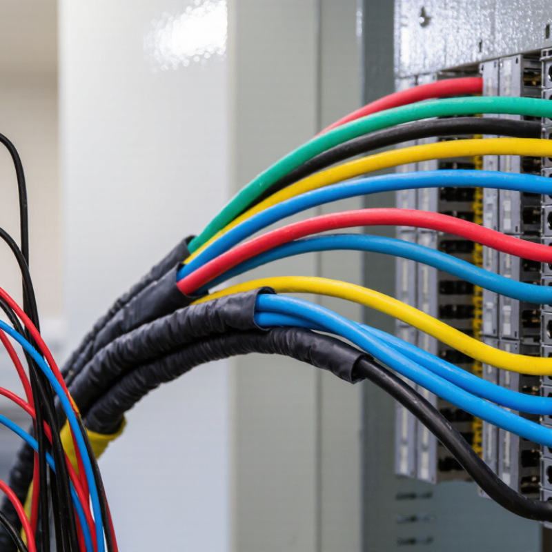
Multi-pair instrumentation cable is a grouped cable containing several separate pairs of insulated conductors. Each pair carries a signal between field instruments and control equipment, such as temperature sensors, pressure transmitters, and monitoring panels. The conductors are often twisted together to help reduce electrical interference. Simple in appearance. Important in practice.
Cable construction varies by installation. Some designs shield each pair; others use one shield around all pairs, or combine both approaches. A metallic foil or braid, sometimes with a drain wire, helps manage interference when installed and grounded according to the system design. The outer jacket protects the cable from abrasion, moisture, and other site conditions, but its rating must suit the actual environment. Check the specification.
In a control room, one cable may carry signals from several instruments, keeping wiring organized between equipment cabinets and field junction boxes. Pair identification also helps technicians trace individual circuits during testing or maintenance. However, the cable does not automatically prevent signal problems. Long runs, nearby power wiring, poor termination, or an unsuitable shield arrangement can still affect performance. That detail is easy to overlook. Choose the number of pairs, conductor size, shielding, and jacket type to match the instruments, installation route, and control system requirements.
How Its Pairs Carry Instrument Signals
Multi-pair instrumentation cable carries several instrument signals through one shared outer jacket. Each twisted pair forms a separate circuit, usually linking a field transmitter to a control-system input. A pressure transmitter, for example, can send its reading over one pair while nearby pairs carry temperature or flow signals. The twist helps reduce electrical noise picked up along the cable run. Shielding may add protection, but the grounding method and cable construction matter.
A common signal is 4–20 mA. IEC 60381-1 specifies this direct-current range for process-control signals: 4 mA represents the live zero, and 20 mA represents the upper range value. With a linear setup, 12 mA represents the midpoint. That is concrete. A receiver can interpret each pair’s current independently, so several measurements travel together without sharing the same signal conductors. Pair count does not guarantee usable channels, though; spare pairs, termination quality, and installation conditions affect what works in practice. Keep signal pairs away from power conductors where the installation design calls for separation. Small routing choices can matter.
Where Multi-Pair Instrumentation Cable Is Used
Multi-pair instrumentation cable connects field devices to control and monitoring systems in process plants. It carries signals from pressure transmitters, temperature probes, flowmeters, and valve positioners to control rooms. You will find it around refineries, chemical plants, power stations, water-treatment facilities, and manufacturing lines. Small signals matter. Separate twisted pairs help reduce interference, while shielding can provide added protection in electrically noisy areas. Correct cable selection still depends on signal type, distance, environment, and installation method.
The IEA’s Energy Efficiency 2023 report says industry accounts for about 37% of global energy use. That scale helps explain why plants rely on continuous measurements to monitor equipment and process conditions. Instrumentation cables also connect sensors and control panels in power facilities; the IEA reported that global electricity demand rose 4.3% in 2024 in its Electricity 2025 report. In the field, cables may run through trays beside pumps, across production floors, or between outdoor instruments and control buildings. Still, routing is rarely perfect. Heat, moisture, vibration, and nearby power cables can affect service life or signal quality, so engineers check the cable specification and installation details for each route.
How Shielding Helps Protect Signal Quality
What Is Multi Pair Instrumentation Cable Used For?
How Shielding Helps Protect Signal Quality
Multi-pair instrumentation cable carries low-level signals between sensors, transmitters, and control equipment. Twisted conductors help reduce magnetic interference because noise can affect both wires similarly. Shielding adds another layer of protection. It matters most where signal cables run near electrical equipment.
A foil shield provides broad coverage, while a braided shield offers flexibility and a conductive path for interference. Some cables combine both. A shield can help reduce electric-field noise from motors, drives, and nearby power wiring when it is bonded appropriately. Pair twisting still matters. Shielding cannot correct poor routing, damaged insulation, or loose terminations.
For example, a long cable beside a motor feeder may carry temperature readings that fluctuate when equipment starts. A suitable shield, sensible cable separation, and grounding based on the instrument design can reduce these disturbances. Grounding both ends without checking the installation can create a ground loop. It is not a perfect fix. Check equipment instructions, and observe signal behavior while the system operates; cable specifications alone cannot guarantee clean readings.
What to Consider When Selecting and Installing It
What Is Multi Pair Instrumentation Cable Used For?
When selecting multi pair instrumentation cable, start with the signals, not the catalogue description. Count the circuits, then check conductor size, insulation, and voltage rating against the equipment requirements. Low-level sensor signals can be vulnerable to electrical noise, so consider individually shielded pairs or an overall shield where needed. More shielding is not automatically better; it can add bulk and complicate termination.
Match the cable construction to its route. A dry control room has different demands from a damp tray or an outdoor run exposed to sunlight. Check the temperature range, jacket material, and any installation-specific requirements. Measure the route, allow sensible service loops, and confirm the cable fits the conduit without being forced. Tight bends can damage insulation or distort the pairs. Small details matter.
During installation, keep instrumentation cable away from power conductors when practical, and cross them at right angles if separation is limited. Follow the equipment design for shield bonding; grounding choices depend on the system, and a universal rule can create noise problems. Label both ends before connecting each pair, then verify continuity and check for shorts. It is tempting to rush this step. That is often where a small wiring error survives unnoticed.
What Is Multi-Pair Instrumentation Cable Used For?
Multi-pair instrumentation cable carries multiple low-level control and measurement circuits between instruments, sensors, and control systems. The chart shows illustrative pair counts for common circuit layouts—not a required standard.
When selecting and installing: Count required circuits and spare pairs; check conductor size, insulation ratings, shielding, grounding, and compatibility with the signal type and environment. Route instrumentation cable away from power cables where practical, and follow applicable electrical codes and manufacturer guidance.